< Back to Proximity Switches
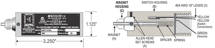
DNFT-PRX
SPECIFICATIONS
Part Number.....................................................000169
..........................................................................000170
..........................................................................000172
Material...............................Stainless Steel, Aluminum
Temperature Range..........................-40 C to +55 C
Switch Rating......................2.5 VA / 200 VDC ½ AMP
Epoxy Encapsulated.................UL LISTED EL-CAST VFR 641
The DNFT PRX was designed and rated for use in Class I Zone I environments, to be used outdoors in wet or dry locations,
in altitudes under 2000 meters, with a Pollution Degree of 4, with no external power required.
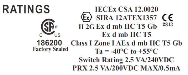
RATINGS
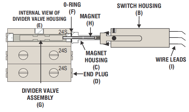
INSTALLATION AND ADJUSTMENT PROCEDURE
1. Loosen all (2) Allen head set screws (A) on switch housing (B) and
remove magnet housing (C). Do not remove magnet, spring, and
spacer from magnet housing.
2. Remove end plug (D) from divider valve where proximity switch
will be installed. Proximity switch can be installed on any available
divider valve section.
3. Screw magnet housing (C) into end of divider valve. Torque to 15
foot pounds max. Be sure 0-ring or metal gasket (F) is in place on
magnet housing (C) if required.
4. Slide switch housing (B) all the way onto magnet housing (C).
Connect ohmmeter to yellow switch leads. Do not tighten set
screws at this time.
5.To properly adjust switch housing (B), divider valve assembly (G)
must be cycling so magnet (H) is moving back and forth. This can be
achieved with lubrication system functioning or by manually
pumping clean oil through divider valve assembly with a hand
pump.
6. If a cycle is not detected, adjustment is made by sliding switch
housing (B) out in 1/16" increments. Continuity meter connected to
yellow wires will indicate a switch closure. Adjust 1/16" out until
correct adjustment is confirmed. Torque set screws to 25 inch
pounds max.
7. Use 10 to 12 inches of flexible conduit on the switch housing for
ease of adjustment or maintenance. All conduit and connections
should be appropriate for area classification. CAUTION: Conduit
and fittings must be supported to avoid bending magnet assembly.
Notice:When installing more than one DNFT, each DNFT must be wired to a separate alarm circuit of the control panel,
annunciator, or PLC to simplify troubleshooting the lubrication system and DNFT.
Note:The DNFT shall be installed in such a way that there is a low risk of mechanical danger.
Warning:DO NOT OPEN when an explosive gas atmosphere is present.
*NOTE A:
Output PRX Wires: The yellow wires are used to connect the DNFT to a PLC, annunciator, or other control monitoring device.
The alarm wires will open and close with each cycle.
Device Operation Wires: The yellow PRX wires will open and close with each cycle, these are used for a PLC input or for
an external totalizer or counter.
Green Ground Wire: The green ground wire is used to ground the DNFT from stray voltages or currents floating around the
natural gas compressor package.
RATINGS
| Ordering Informaiton
|
| Model |
Description |
Part Number |
| DNFT-PRX-D |
DROPSA |
000169 |
| DNFT-PRX-L |
LINCOLN - O-RING STYLE |
000170 |
| DNFT-PRX-TO |
TRABON - O-RING STYLE “1995” AND LATER |
000172 |
< Back to Proximity Switches