TROUBLESHOOTING DNFT-PRG-PS
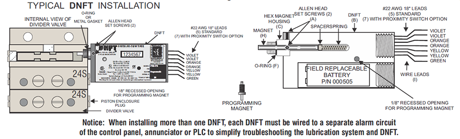
NOTICE: WHEN MORE THAN ONE DNFT IS INSTALLED ON THE COMPRESSOR OR ENGINE, EACH DNFT MUST BE WIRED TO A SEPARATE ALARM
CIRCUIT ON THE CONTROL PANEL, ANNUNCIATOR OR PLC TO SIMPLIFY TROUBLESHOOTING THE LUBRICATION SYSTEM AND DNFT.
P/N 000518 DNFT-PRG-PS PROGRAMMABLE DIGITAL NO-FLOW TIMER
INSTALL ON TRABON* DIVIDER BLOCK WITH O-RING SEALS. SWITCH RATING 2.5VA / 240VDC
NOTICE: DNFT-PRG MUST BE PROGRAMMED BEFORE INSTALLING ON DIVIDER VALVE (SEE PROGRAMMING INSTRUCTIONS)
1. Loosen all Allen head set screws (A) on DNFT (B) and remove magnet housing (C). Do not remove magnet, spring or
spacer from magnet housing.
2. Remove piston enclosure plug (D) from end of divider valve where DNFT will be installed. The DNFT does not have to be
installed on the top divider valve. It may be installed on any convenient divider valve, top to bottom. (Notice: Do not install
DNFT on Lincoln divider valves with cycle indicator pins or any Dropsa divider valve less than SMX 16.)
3. Be sure O-ring or metal gasket (F) is in place on magnet housing (C). Screw magnet housing (C) into end of divider valve
(E). Torque to 15 foot pounds max.
4. Slide DNFT (B) all the way onto hex of magnet housing (C). Tighten set screws on hex of magnet housing. Torque25 inch
pounds max.
5. If number on LCD (G) does not change, or LED does not blink, DNFT must be adjusted. Before adjusting DNFT, divider
valve must be cycling with compressor running or by manually pumping oil into the divider valve. Notice: The self-check
circuitry indicates normal operation and battery voltage by a continuous faint blink of the LED. Normal cycle indication is a
bright strobe type blink.
6. Adjustment is made by sliding the DNFT (B) all the way on the hex of the magnet housing (C). Tighten set screws on hex
of the magnet housing to 25 inch pounds max. If there is no change on the LCD or the LED does not blink, adjust the DNFT
back in 1/16" increments. Correct adjustment of the DNFT is confirmed by number change on the LCD or the LED blinking.
7. All conduit and connections should be appropriate for area classification. Notice: Conduit and fittings must be supported
to avoid bending magnet housing.
8. After installing magnet assembly and pre-compressor start-up, it is absolutely necessary to purge all air from
divider block lubrication system. This can easily be accomplished with a lubrication system purge gun.
9. DNFT must be installed with correct magnet assembly for each divider valve manufacturer.
Lincoln-7/16"-20 extended nose with O- ring Dropsa
Trabon-1994 or earlier 7/16"-20 with metal crush gasket Trabon-1995 and later 7/16"-20 with O-ring
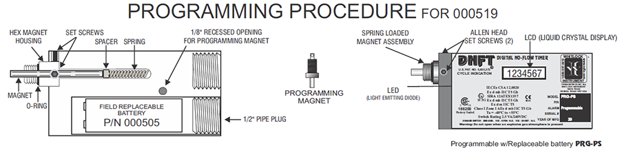
Programming Modes Available:
MODE 1- Displays Total Divider Valve Cycles. Program Alarm Time in Seconds. MAX: 255 Sec. (4 Min. 15 Sec.) MIN: 20 Seconds
MODE 2 - Displays Cycle Time of Divider Valve in Seconds
MODE 3 - Displays Total Pints. Program Divider Valve Total: Maximum of 120
MODE 4 - Displays Pump Rate in Pints Per Day
To program the DNFT, the programming magnet must be inserted into the 1/8" recessed opening located on the face of the DNFT. To change
programming mode, remove and re-insert the programming magnet into the recessed opening. The current programming mode 1,2,3 or 4 will
immediately be displayed followed by a "0" 2 seconds later. This "0" indicates that the current mode may be programmed.
NOTICE: DNFT MUST BE PROGRAMMED BEFORE INSTALLATION ON DIVIDER BLOCK.
Mode 1 - LCD Displays Total Divider Valve Cycles. Program Alarm Time MAX: 4 Minutes 15 Seconds (255 seconds)MIN: 20
Seconds
Insert programming magnet into the 1/8" recessed opening located on the face of the DNFT. If mode 1 is not selected in display, remove and reinsert
programming magnet until the LCD indicates mode 1. Do not remove programming magnet when mode 1 is displayed. To set alarm time,
depress and release spring loaded magnet assembly until desired alarm time (in seconds) is displayed on the LCD. Example: 60 counts on LCD
=60 second alarm time. Remove programming magnet. DNFT will display total divider valve cycles if left in this mode and is now set for 60
Mode 2 - LCD Displays Cycle Time of Divider Valve in Seconds. LCD will count each cycle of the divider valve in seconds, counting
up from "0" until the divider valve completes one full cycle. When divider valve completes one full cycle, the LCD will reset to zero and begin
counting each second until another cycle is completed.
Mode 3 - LCD Displays Total Pints Used. Program Divider Valve Total in This Mode. MAXIMUM DIVIDER VALVE TOTAL: 120
Insert programming magnet into 1/8" recessed opening located on the face of the DNFT. If mode 3 is not selected in display, remove and reinsert
programming magnet until the LCD indicates mode 3. Do not remove programming magnet when mode 3 is displayed. To program divider
valve total, add the total of the divider valve assembly on which the DNFT will be installed. Example: 24 + 24 + 24 = 72. Enter the total of the
divider valve assembly by depressing and releasing the spring loaded magnet until the divider valve total is displayed on the LCD. When the total
of the divider valve assembly is displayed, remove the programming magnet. The DNFT is now programmed and will record total pints on the
LCD if left in mode3. The LED blinks in all modes to indicate each divider valve cycle. This blink enables the operator to set pump rate.
Mode 4 - LCD Displays Pump Rate in Pints Per Day . FOUR (4) SECOND MINIMUM CYCLE TIME.
CAUTION: DO NOT INSERT PROGRAMMING MAGNET IN THE RECESSED OPENING WHEN THE UNIT IS MOUNTED ON DIVIDER
VALVE WITH COMPRESSOR RUNNING. DNFT WILL GO INTO ALARM AND COMPRESSOR WILL SHUTDOWN. MODES CANNOT BE
CHANGED WHILE DNFT IS MOUNTED ON DIVIDER VALVE WITH COMPRESSOR RUNNING.
DNFT must be removed from the divider valve to change modes. After removing DNFT from divider valve, operator may change to any mode by
inserting and removing programming magnet until desired mode is displayed by LCD. Please Note: DNFT will store all programmed information
until programming magnet is inserted and spring loaded magnet is depressed. If spring loaded magnet is depressed with programming magnet
in place, unit defaults to zero and must be reprogrammed.
DNFT BATTERY REPLACEMENT INSTRUCTIONS
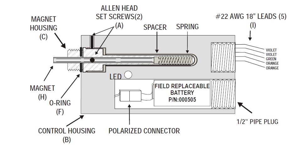
1. Shut down the engine or set the bypass timer.
2. Use a 3/8" ratchet to remove the 1/2" NPT Pipe plug.
3. Remove the battery from the DNFT and disconnect from the polarized connector.
4. Connect the new battery to the attached polarized plug.
5. Reinsert the battery and reinstall 1/2" NPT Pipe plug.
6. Verify the DNFT is working by pre-lubing the system and check for LED blink.
ITEMS REQUIRED FOR REPLACING THE DNFT BATTERY:
(1) P/N: 000505 BATTERY or RADIO SHACK P/N: 960-0418 (alternate replacement)
(1) 3/8“ RATCHET WRENCH (for removal of battery plug)
< Back to DNFT