< Back to DNFT

DNFT-LED P/N: 000506


MONITORS MOVEMENT OF DIVIDER VALVE PISTON FOR DEPENDABLE "TIMED" SHUTDOWN PROTECTION

CLOSED LOOP OR OPEN LOOP OPERATION

INSTALLS DIRECTLY TO DIVIDER VALVE

NOT AFFECTED BY TEMPERATURE OR OIL VISCOSITY

REQUIRES NO EXTERNAL POWER

LED INDICATOR - CYCLE INDICATION

DEDICATED SWITCH CLOSURE TO MONITOR EACH DIVIDER VALVE CYCLE (PS OPTION 000507 ONLY)

FIELD REPLACEABLE BATTERY

SPECIFICATIONS

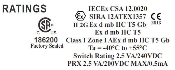
Temperature Range.............................................. -40C to +55C
Switch RaTing........................................................2.5VA/240 VDC
PRX Rating............................................2.5VA/200 VDC MAX/0.5A
Epoxy Encapsulated.......................UL LISTED EL-CAST VFR 641
Alarm/Shutdown........................ Factory default for 2 minute alarm
Power......................................Field Replaceable - Lithium Battery
.......................................3.6 Volt, 1.5Ah, 75mA MAX Contentious Current
Battery........................................................................ P/N 000505
Divider Block Application............Dropsa/Lincoln/SBCO/Lubriquip
Warranty.........................................................................2.5 Years

RATINGS


DESCRIPTION

The DNFT-LED is a totally enclosed electronic device, combining the latest technology in microprocessor and transistor components for detecting Slow-Flow and No-Flow of divider block lubrication systems. The DNFT incorporates an oscillating crystal to accurately monitor the cycle time of the lubrication system to enable precision timed shutdown capability. The magnet assembly and control housing mount directly to the divider valve to become an integral part of the lubrication system. The DNFT operates on a field replaceable lithium battery. If battery voltage drops below normal operating levels the DNFT goes into alarm mode and the unit cannot be restarted. LED models utilize an LED to indicate each cycle of the divider valve. This enables the operator to easily set and monitor lubrication rates. The DNFT has been designed and rated for use in Class I Zone I environments, to be used outdoors in wet or dry locations, in altitudes under 2000 meters, with a Pollution Degree of 4.


OPERATION

Lubricant flow through the divider valve assembly forces the pistons to cycle back and forth causing a lateral movement of a magnet linked to the piston. Movement is monitored by the microprocessor which resets the timer, lights the LED, and allows the unit to continue operation, this indicates one complete cycle of the lubrication system. The microprocessor must receive this cycle in a predetermined time or a shutdown will occur. The DNFT will automatically reset alarm circuit when normal operation of divider valve resumes.


1. Loosen all Allen head set screws (A) on DNFT (B) and remove magnet housing (C). Do not remove magnet, spring or spacer from magnet housing.

2. Remove piston enclosure plug (D) from end of divider valve where DNFT will be installed. The DNFT does not have to be installed on the top divider valve. It may be installed on any convenient divider valve, top to bottom. (Notice:Do not install DNFT on Lincoln divider valves with cycle indicator pins or any Dropsa divider valve less than SMX 16.)

3. Be sure O-ring or metal gasket (F) is in place on magnet housing (C). Screw magnet housing (C) into end of divider valve (E). Torque to 15 foot pounds max.

4. Slide DNFT (B) all the way onto hex of magnet housing (C). Tighten set screws on hex of magnet housing. Torque 25 inch pounds max.

5. The LED on the DNFT indicates each divider valve cycle. This enables operator to adjust the lubricator pump for correct cycle time and oil consumption recommended by compressor manufacturer. If LED does not blink with compressor running or by manually pumping oil into divider valve, the DNFT must be adjusted. Normal cycle indication is a bright strobe type blink.

6. Before adjusting DNFT, divider valve must be cycling. This can be achieved with the compressor running or by manually pumping oil through the divider valve assembly with a hand priming pump.

7. Adjustment is made by sliding the DNFT (B) all the way on the hex of the magnet housing (C). Tighten set screws on hex of the magnet housing to 25 inch pounds max. Check for LED blink to confirm correct adjustment. If LED does not blink with divider valve cycling, adjust the DNFT back in 1/16" increments. Correct adjustment of the DNFT is confirmed by blinking LED.

8. All conduit and connections should be appropriate for area classification. Notice: Conduit and fittings must be supported to avoid bending magnet housing.

9. After installing magnet assembly and pre-compressor start-up, it is absolutely necessary to purge all air from divider block lubrication system. This can easily be accomplished with a lubrication system purge gun.

10.DNFT must be installed with correct magnet assembly for each divider valve manufacturer.
Lincoln-7/16"-20 extended nose with O- ring............................. Dropsa
Trabon-1994 or earlier 7/16"-20 with metal crush gasket.......... SBCO & Trabon-1995 and up 7/16"-20 with O-ring


TROUBLESHOOTING DNFT-LED

NOTICE: WHEN MORE THAN ONE DNFT IS INSTALLED ON THE COMPRESSOR OR ENGINE, EACH DNFT MUST BE WIRED TO A SEPARATE ALARM CIRCUIT ON THE CONTROL PANEL, ANNUNCIATOR OR PLC TO SIMPLIFY TROUBLESHOOTING THE LUBRICATION SYSTEM AND DNFT.

TYPICAL DNFT INSTALLATION

Magnet Assemblies and Applications

DNFT must be installed with correct magnet and Applications assembly for each divider valve manufacturer.


DNFT BATTERY REPLACEMENT INSTRUCTIONS


Directions for replacing the battery in the Digital No Flow Timer

1. Shut down the engine or set the bypass timer.

2. Use a 3/8" ratchet to remove the 1/2" NPT Pipe plug.

3. Remove the battery from the DNFT and disconnect from the polarized connector.

4. Connect the new battery to the attached polarized plug.

5. Reinsert the battery and reinstall 1/2" NPT Pipe plug.

6. Verify the DNFT is working by pre-lubing the system and check for LCD number change.

ITEMS REQUIRED FOR REPLACING THE DNFT BATTERY:
(1) P/N: 000505 BATTERY or RADIO SHACK P/N: 960-0418 (alternate replacement)
(1) 3/8“ RATCHET WRENCH (for removal of battery plug)

< Back to DNFT